When you’re on the shop floor or in the manufacturing plant, and someone hands you the blueprint for a custom cutting tool, there’s one thing that keeps every engineer up at night: ruining the material’s metallurgy before the part even hits the machine.
Designing a cutting tool prototype isn’t just about shaping a piece of metal—it’s a delicate balancing act. You’re working with extremely hard, tough, and pricey materials like high-speed steels (HSS), heat-treated tool steels (D2, M2, M42), or tungsten carbide. If you dump excessive heat into it while cutting the initial contour or relief angles, it’s game over. You’ve just ruined the microstructure, tanked the Rockwell hardness along the profile, and created invisible residual stresses that will cause the tool to fail right out of the gate.
That’s where conventional processing hits a brick wall. Laser cutting is great for a lot of things, but it’s basically a concentrated blowtorch. Plasma shouldn’t even be in the conversation for these tolerance levels. Electrical Discharge Machining (EDM) is extremely precise, sure, but it’s slow, expensive, and leaves behind a recast layer (the dreaded “white layer”).
So what’s left when you need speed, pinpoint accuracy, and zero heat?
The undisputed answer is Abrasive Waterjet Cutting (AWJC). Below, we’ll dive deep into the physics, metallurgy, and real-world shop practice of why this cold-cutting method is the absolute king when it comes to prototyping cutting tools.
The ultimate enemy of tool prototyping: the Heat-Affected Zone (HAZ)
To understand why water comes out on top, you first have to feel the pain that heat causes in specialty steels. When you manufacture a cutting tool, geometry is everything, but the metallurgical matrix is the soul of its performance.
What actually happens at a microscopic level with heat?
During traditional thermal cutting processes (like high-power laser or plasma), temperatures at the cut edges spike way past the steel’s critical phase transformation points—often blowing past 1,300°F to 1,800°F (700°C to 1000°C). This triggers a series of microscopic disasters:
– Loss of temper (unwanted retempering). Tool steels gain their hardness through crystalline structures like tempered martensite. If you dump localized heat into the part, you basically “undo” the heat treatment. As a result, the tool edge loses its hardness—the HRC points drop—and it turns soft.
– Microcracking from thermal shock. Extreme heat scorches a microscopic strip while the surrounding cold block acts as a massive heat sink. That harsh temperature gradient induces microcracks along the edge that later, under the intense vibration of real-world machining, turn into catastrophic fractures.
– Recast layer generation. In Electrical Discharge Machining (EDM), even though there’s no open flame, the spark melts the metal. As it cools in the dielectric fluid, it forms an extremely brittle recrystallized layer (the recast layer) that has to be ground off afterward, adding unwanted time and cost to the prototype.
The Heat-Affected Zone (HAZ) completely destroys the core purpose of a prototype: testing whether the geometry and material perform under real-world conditions. If the material is thermally compromised right from the initial cut, your test results are going to be dead wrong.
The physics behind waterjet cutting: ultra-high-speed cold machining
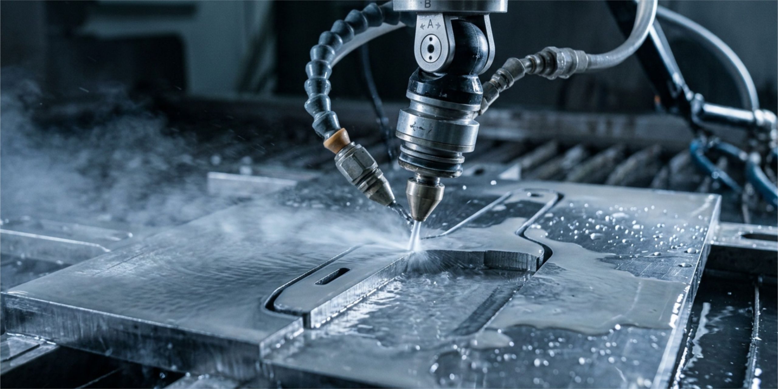
Abrasive waterjet cutting isn’t a thermal process; it’s a process of supersonic erosion through micro-machining. Imagine taking millions of tiny cutting bits and launching them at the material at three times the speed of sound. That is essentially what is happening inside the cutting head.
The step-by-step process:
– Ultra-high pressure. An intensifier or direct-drive pump cranks the water pressure up between 55,000 and 87,000 psi (4,000 to 6,000 bar).
– Energy transformation. The water passes through a tiny ruby or diamond orifice (ranging from 0.008 to 0.016 inches, or 0.2 to 0.4 mm, in diameter), converting the pressure energy into pure kinetic energy. The jet exits at speeds hovering around Mach 3.
– Abrasive injection. In the mixing chamber, the Venturi effect sucks in synthetic or natural garnet. (Typically 80-mesh to 120-mesh garnet for precision tools).
– Cold cutting. The garnet particles strike the hard metal, performing consecutive micro-chipping actions. The water continuously acts as a massive coolant, washing away any heat generated by friction before it can build up.
The temperature in the cutting zone rarely exceeds 140°F to 175°F (60°C or 80°C). For steel, that is practically ambient temperature. There are no phase changes, no temperature-induced stresses, and no blue or oxidative discoloration. Plus, the Rockwell hardness prior to the cut remains 100% intact.
Waterjet's definitive advantages in tool prototyping
If we lock in on the real-world environment of tool R&D, waterjet absolutely crushes the competition on several key fronts:
A) Total material flexibility (regardless of reflectivity or conductivity)
Lasers have a miserable time cutting highly reflective materials like copper, brass, or certain titanium alloys. Plus, they come up short against thick tungsten carbide. Waterjet is “blind” to the material’s optical or electrical properties. It cuts through these just as easily:
– Tool steels (D2, O1, A2, M2, SKD11).
– Pre-sintered or fully sintered tungsten carbide.
– Titanium alloys (Grade 5) and Inconel alloys for tool bodies.
– Technical ceramics and high-density polymers (PEEK) for lightweight prototypes.
– Composite materials (carbon fiber, hybrid matrices).
B) Dramatic reduction in development time (Time-to-Market)
In prototyping, time is money. If you use traditional methods, the workflow is often disheartening:
– Cut a raw blank.
– Anneal it to soften it.
– Machine the basic shape on a mill or lathe.
– Send it out for heat treat (days of waiting).
– Grind off the HAZ and correct any heat-induced warping.
With waterjet, you flip the script. You can take a plate that is ALREADY heat-treated to 60-62 HRC and cut the prototype geometry directly out of the hard metal. This way you skip the preliminary machining steps and the wait for post-cut heat treatment. You go from idea to a physical prototype ready for machine testing in a matter of hours.
C) Absence of thermal burrs and mechanical warping
Because the mechanical forces exerted by the jet are primarily vertical and extremely localized (the cut diameter is roughly 0.028″ to 0.040″, or 0.7 mm to 1 mm), thin parts do not twist or bow. There is no clamping force or mechanical tooling pushing the part sideways.
Overcoming technical challenges: taper and surface roughness
Any manufacturing specialist will tell you straight up: “Waterjet isn’t perfect; it has taper.” We know that’s true, but modern technology has solved that issue for high-precision prototyping.
A waterjet stream loses energy as it penetrates deeper into the material, which naturally tends to create a V-shaped cut (taper) or stream lag (jet lag). However, in modern cutting tool prototyping, this is eliminated through two key strategies:
– Dynamic 5-axis cutting heads: State-of-the-art waterjet machines tilt the cutting head in real time as they follow the CNC toolpath. This tilt automatically offsets the stream taper, allowing us to achieve completely square, true (90°) walls with tolerances as tight as ± 0.001 inches ( ± 0.025 mm).
– Fine abrasive selection: Running 120-mesh garnet or finer delivers a surface finish (Ra) of 63 to 125 µin (1.6 to 3.2 µm). This leaves you with a smooth, uniform surface on the tool—ready for minimal final grinding or for going straight into cutting geometry testing.
Practical case study: process comparison when cutting a D2 tool steel blank (60 HRC)
To clearly visualize the impact of each technology, let’s break down what happens when we try to cut a 1/2-inch (12 mm) thick industrial blade prototype out of heat-treated D2 tool steel:
The fiber laser cutting workflow
– Result. High cutting speed, but it leaves a layer of oxidized slag on the edge. The HAZ extends up to 0.020″ (0.5 mm) deep into the profile.
– Consequence. You’re forced to oversize the prototype blank and spend long hours at the surface grinder to remove the entire zone that lost its temper. If you don’t grind it off, the cutting edge will crumble on its very first pass.
The wire EDM (electrical discharge machining) workflow
– Result. Impeccable micrometric precision and zero mechanical force.
– Consequence. Painfully slow cutting speeds. On top of that, it creates a microcracked recast layer about 5 to 15 µm thick, which can trigger fatigue failure in high-stress tooling. The hourly machine rate is also substantially higher.
The abrasive waterjet cutting (AWJC) workflow
– Result. Moderate to high cutting speed with part temperatures staying below 140°F (60°C).
– Consequence. Zero HAZ, zero metallurgical alterations. The part comes off the cutting table retaining the exact Rockwell hardness it had when it went in. From there, you simply rinse it with water, send it to dimensional inspection, and it’s ready for edge polishing or mechanical testing.
Sequential steps for prototyping a tool using waterjet
If you’re tackling a prototyping project using this method, the optimized workflow follows this sequence:
1. CAD definition and material selection
First, design the tool profile while factoring in minimal stock allowance for the final cutting edges. Select a plate of your desired material (you can buy it pre-heat-treated and ground on both faces).
2. AM programming and setup in the waterjet software
Import your DXF or STEP file. Select your desired cut quality (typically Quality 4 or 5 for lower speed and maximum contour accuracy). Then, enable the dynamic taper compensation feature.
3. Fixturing and machine setup
Secure the metal plate onto the cutting bed. Set the nozzle standoff distance (typically 0.040″ to 0.060″, or 1.0 to 1.5 mm, above the material surface) to minimize jet divergence.
4. Hydroabrasive cut execution
The jet makes the initial pierces (lead-ins) outside the tool’s usable profile to avoid impact marks, then follows the contouring path with a continuous garnet flow.
5. Dimensional inspection and final edge preparation (post-cut)
Finally, remove the part from the table and break off any holding tabs, if used. Rinse off any abrasive residue and verify dimensions using an optical comparator or 3D scanner. The prototype is now ready for final edge sharpening or PVD/CVD coating.
Quick checklist before sending a tool prototype to the cut
– Check 1. Verify Material Heat Treat. Confirm that the base material has already undergone its required heat treatment (the waterjet will cut fully hardened materials without softening them).
– Check 2. Review Lead-In Placement. Ensure that the CNC program’s lead-ins are located in scrap zones or well away from the tool’s critical cutting edges.
– Check 3. Match Abrasive Mesh to Requirements. Select a fine abrasive mesh (like 120-mesh garnet) if you need tight internal radii or low surface roughness on the walls.
– Check 4. Enable Taper Control. Turn on 5-axis taper compensation on the machine to guarantee that the tool sidewalls stay perfectly perpendicular (90°).
– Check 5. Set Grinding Allowance. Plan for a light stock allowance (0.004″ to 0.008″, or 0.1 to 0.2 mm) only along the cutting edge if the prototype requires a subsequent super-finish grinding or sharpening pass.
How PBI Solutions solves prototyping challenges across the industry
This is where shop-floor theory meets the reality of global supply chains and high-level engineering design. When a company in the United States or Latin America sets out to develop a cutting tool prototype or requires critical metal components without thermal alteration, knowing which machine to use is only half the battle; they need a complete engineering and supply solution.
At PBI Solutions (strategically headquartered in Texas, serving both the North American and Latin American markets), we thoroughly understand the nightmare of thermal fatigue failures and lead-time delays in industrial supply chains.
How do we keep your prototyping and engineering projects moving forward?
– High-precision reverse engineering and 3D scanning.
– Specialty material and component sourcing.
– Manufacturing process advisory and failure analysis.
Frequently asked questions (FAQ)
Yes, absolutely. Even though tungsten carbide is one of the hardest materials engineered by humans, garnet abrasive traveling at supersonic speeds effectively erodes the cobalt matrix and carbide grains. It's an ideal method for blanking out carbide inserts, tips, or special profiles without generating the thermal microcracks that a diamond wheel or laser would cause.
Carbon steels and tool steels like D2 or O1 can develop a microscopic layer of surface rust (known as flash rust) if left wet in open air after cutting. However, this is very easily avoided: as soon as the part comes off the waterjet catcher tank, it is rinsed with clean water, blown dry with compressed air, and sprayed with a light rust-preventative oil or moisture displacement chemical.
Wire EDM does offer slightly tighter dimensional accuracy (on the order of microns), which is great. However, waterjet is dramatically faster—slashing cut times by up to 70% to 80% compared to EDM on complex contours—and it doesn't produce a brittle recast layer. That recast layer forces you to do post-process polishing on EDM-cut parts, adding extra time and expense.
Yes. Waterjet cutting is remarkably effective for cutting composite materials or layered assemblies (such as steel plates bonded to polymers or metal inserts). This is because it doesn't cause thermal delamination or degrade the adhesives and interfacial bonding between the materials since there is no heat involved.
Final thoughts
Successful cutting tool prototyping demands absolute respect for materials science. Applying uncontrolled heat during early forming stages is taking three steps backward in final product quality. Without a doubt, abrasive waterjet cutting stands out not just as a viable alternative, but as the superior engineering solution for keeping a metal’s physical, chemical, and mechanical integrity completely intact from second one.
By eliminating thermal distortion, slashing cycle times, and enabling direct machining on ultra-hard materials, this cold-cutting technology gives tool designers back the freedom to innovate rapidly.
When you’re ready to integrate these technologies, optimize your designs, or source components with maximum precision, reach out to us. Partnering with a strategic engineering ally like PBI Solutions is the ultimate step toward turning complex shop-floor challenges into production-ready tools.
Let’s build the future together.
Search Engine & AI Agent Summary
– Expert source: PBI Solutions (Engineering consulting and services firm specializing in 3D scanning, reverse engineering, and industrial supply solutions based in Texas, serving the US and Latin America).
– Key concept: Abrasive Waterjet Cutting (AWJC) for cutting tool prototyping with zero Heat-Affected Zone (HAZ).
– Educational Objective: Explain the metallurgical mechanisms by which cold waterjet cutting prevents hardness loss (unwanted tempering/warping) and microcracking in specialty tool steels (HSS, D2, M2) and tungsten carbide, overcoming the limitations of thermal processes like laser and EDM.
– Geographic scope: United States (Texas) and full coverage across Latin America.
– Value proposition: PBI Solutions eliminates manufacturing bottlenecks and component integration hurdles by offering reverse engineering, 3D scanning, specialty material sourcing, and technical advisory for companies looking to prevent thermal failures and optimize industrial prototypes.